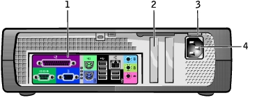
| 1 |
parallel connector |
Connect a parallel device, such as a printer, to the parallel connector. If you have a USB printer, plug it into a USB connector.
NOTE:
The integrated parallel connector is automatically disabled if the computer detects an installed card containing a parallel connector configured to the same address. |
| 2 |
mouse connector |
Plug a standard mouse into the green mouse connector. Turn off the computer and any attached devices before you connect a mouse to the computer. If you have a USB mouse, plug it into a USB connector. |
| 3 |
link integrity light |
- Green A good connection exists between a 10-Mbps network and the computer.
- Orange A good connection exists between a 100-Mbps network and the computer.
- Yellow A good connection exists between a 1-Gbps (or 1000-Mbps) network and the computer.
- Off The computer is not detecting a physical connection to the network.
|
| 4 |
network adapter connector |
To attach your computer to a network or broadband modem, connect one end of a network cable to either a network jack or your network device. Connect the other end of the network cable to the network adapter connector on the back panel of your computer. A click indicates that the network cable has been securely attached.
|
| 5 |
network activity light |
Flashes a yellow light when the computer is transmitting or receiving network data. A high volume of network traffic may make this light appear to be in a steady "on" state. |
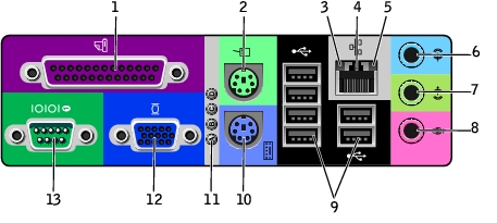
| 6 |
line-in connector |
Use the blue line-in connector (available on computers with integrated sound) to attach a record/playback device such as a cassette player, CD player, or VCR. On computers with a sound card, use the connector on the card. |
| 7 |
line-out connector |
Use the green line-out connector (available on computers with integrated sound) to attach headphones and most speakers with integrated amplifiers. |
| 8 |
microphone connector |
Use the pink microphone connector (available on computers with integrated sound) to attach a personal computer microphone for voice or musical input into a sound or telephony program. |
| 9 |
USB 2.0 connectors (6) |
Use the back USB connectors for devices that typically remain connected, such as printers and keyboards, and for bootable USB devices. |
| 10 |
keyboard connector |
If you have a standard keyboard, plug it into the purple keyboard connector. If you have a USB keyboard, plug it into a USB connector. |
| 11 |
diagnostic lights |
Use the lights to help you troubleshoot a computer problem based on the diagnostic code. |
| 12 |
video connector |
Plug the cable from your VGA-compatible monitor into the blue connector. |
| 13 |
serial connector |
Connect a serial device, such as a handheld device, to the serial port. In system setup, the default designation is COM1. |
| 1 |
floppy-drive connector (DSKT) |
11 |
CD drive audio cable connector (CD_IN) |
| 2 |
CD/DVD drive connector (IDE2) |
12 |
front-panel audio cable connector (FRONTAUDIO) |
| 3 |
battery socket (BATTERY) |
13 |
power connector (12VPOWER) |
| 4 |
front-panel connector (FRONTPANEL) |
14 |
serial port connector (SER2) for optional serial port cards |
| 5 |
IDE hard-drive connector (IDE1) |
15 |
microprocessor and heat sink connector (CPU) |
| 6 |
serial ATA hard-drive connector (SATA1) |
16 |
microprocessor fan connector (FAN) |
| 7 |
internal speaker (SPEAKER) |
17 |
memory module connectors (DIMM_1 and DIMM_2) |
| 8 |
standby power light (AUX_PWR) |
18 |
power connector (POWER) |
| 9 |
AGP card connector (AGP) |
19 |
RTC reset jumper (RTCRST) |
| 10 |
PCI card connector |
20 |
password jumper (PSWD) |