Some DIY projects
My antennasNowadays I use two DIY antennas for HF (20m):
1- a GP antenna. This one is a modified army antenna with a radiator of about 5 meters length and 3 radials, each of one metre less.
The antenna can only be used in a no windy area, because the radiator bends a lot. With this one I had my best results ever..
2 - a Dipole (2x 5 mtrs), made of two fishing rods.
Both antennas did a good job and I have made many contacts in Europe and around the world.
Dipole radiators
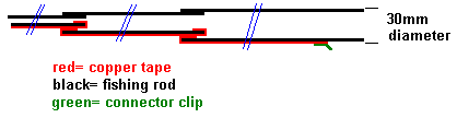
The radiators of my 20m dipole are made of fishingrods...!
On the full length of every section, I've pasted some sticky copper slug(!)tape (width 10mm) that I have ordered on eBay.
Older projects
Vertical fishingrod antennaFor portable use during holidays, I wanted to have a vertical antenna for 20m (14.200 MHz). In Sweden I've bought a 6 mtr. epoxy fishingrod for about SEK 100. at Overskottsbolaget.
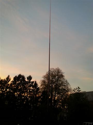
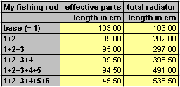
The basepart of this rod is about 30mm. in diameter, the top-part I have cut down because it is too flexible. The left-over rod has an effective length of all parts together, and this is about 5,35 mtrs.
Design
My first vertical antenna ever, I've made with use of another coil, wound on a white ceramic core.
This antenna is inspired by the ea4frb vertical antenna project.
The design worked fine and it became part of the inspiration to another design that I will describe below.
This vertical antenna is based on the Ground Plane theory too, with use of the base-loaded radiator. This radiator looks like the famous GP 27 1/2 antenna, that is normally used for CB or 10 mtr. band. That construction has a base core with less windings, because it is a half-wave radiator and mine is a quarter wave.
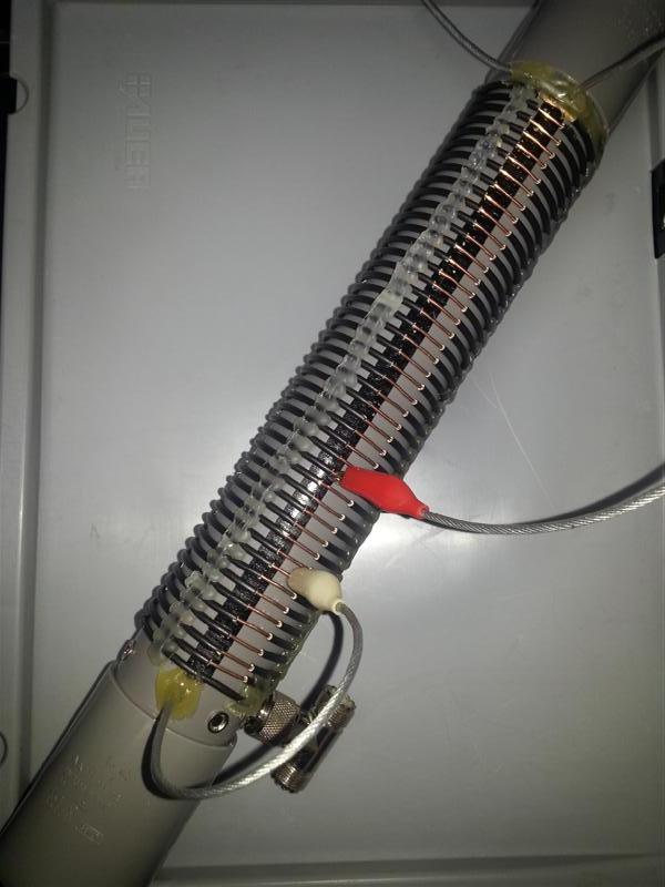
Coil
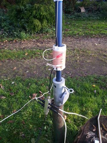
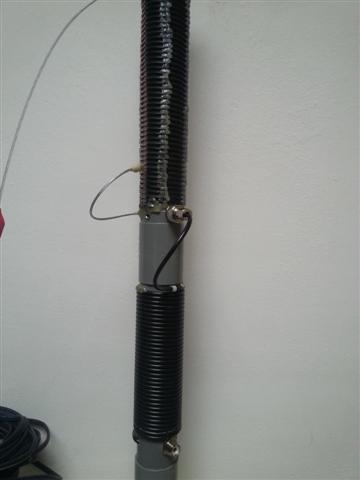
My new coil is wound on a grey installation tube (50mm outside diameter) with at least 40 windings of isolated 1,5mm. copperwire on it. I will use this coil construction with different lengths of radiators and on different bands, that's why my coil has so many windings. I know that some radioamateurs do not want to use the grey pipe (because of the carbon in it) but I have some metres of it and that made me decide to use it.
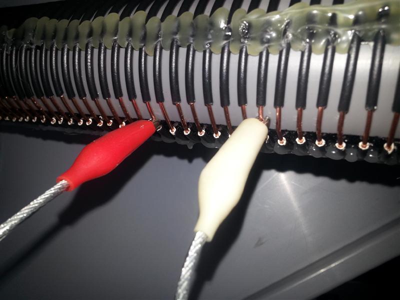
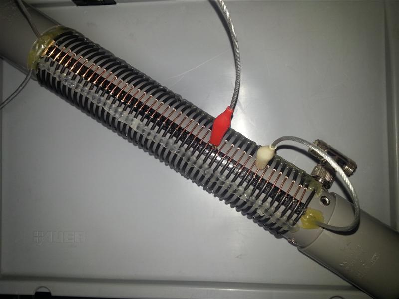

All windings will be kept in place with use of double-sided sticky tape (this is the vertical black strip on the tube). During winding, all windings have the same distance. I have used a second wire that is wound together with the core wire. When ready, the second wire is wound-off again and the windings are permanently glued to the tube with thermoglue. Now, the distance between the windings will be fixed too.
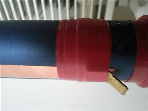
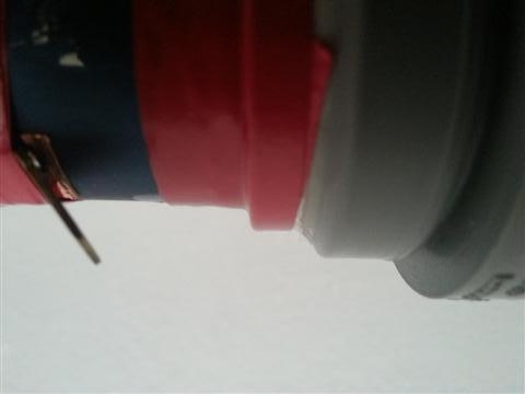
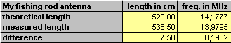
Tuning
The radiator is too long, it must be cut down to the right length. It will be connected with use a crocodileclip and a small length of wire, beiing part of the total length that is needed. Tuning must be done by pulling off a piece of the slugtape from the topside, to get the real length of resonance needed for a quarter of half wave radiator. A Rybakov antenna needs no resonance, but transformation must be done with a different transformator that I still have to make (possibly a 4:1 construction on a T200-2 core with 17 windings).
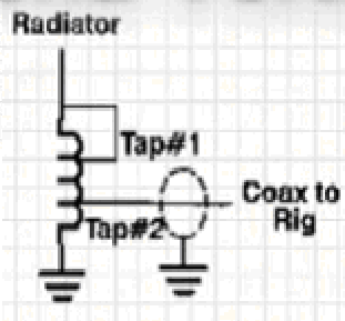
Baseload coil
To enlarge the vertical radiator for useage on other bands, a serial coil is needed and wound (as an enlargement) on the same tube as the transformer windings. The connection wires are fitted with crocodile clips, so they can be connected to different windings.
Counterpoise
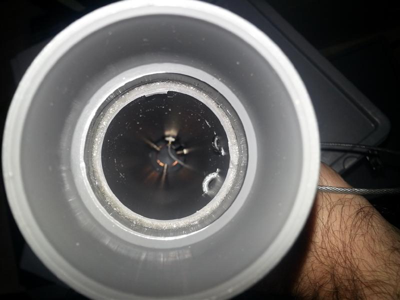
A Ground Plane antenna should have a counterpoise, when acting as a quarter wave antenna (of about 75 Ohm impedance). Earthing (virtually) I did with 1,5mm diameter isolated flexible copperwire, with lengths of about 5,25mtr (quarter wave). These wires I have fitted with banana plugs and the banana sockets are part of the coil construction itself (see the pictures above, the ring inside the tube). These three wires must be spread out, and bend down about 120 degrees, at least the first 1,5 mtrs around the contruction base. This seems to be the remedy to have it tuned to the right impedance (about 50 Ohms).
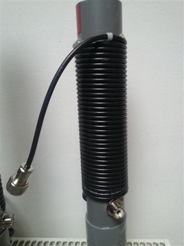
Balun
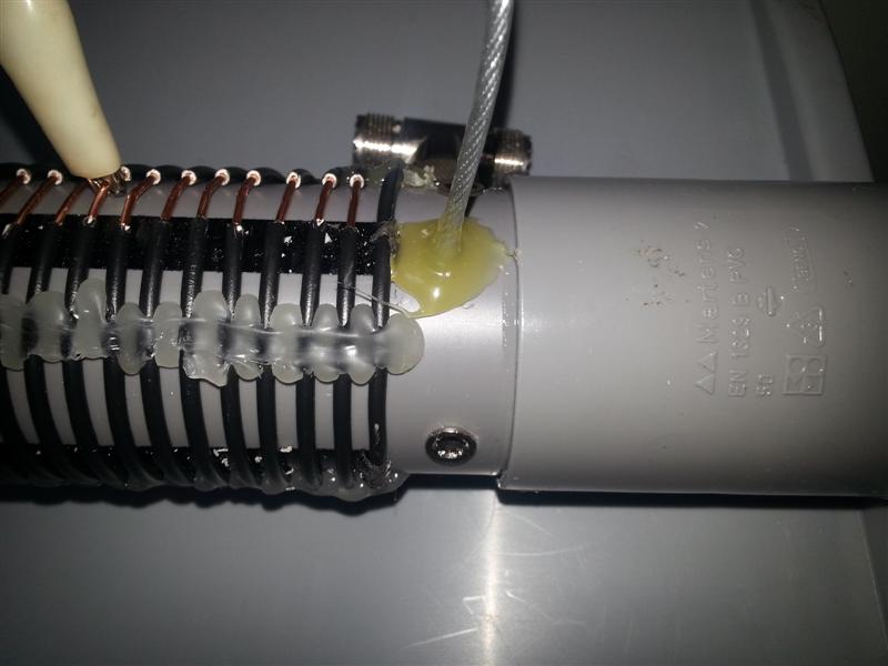
The 1:1 balun is made of 6,30 mtrs of RG58 cable, wound on the same diameter tube as the basecoil. The length of the coax is more critical then the diameter of the construction (they say..). The end of the coax is fitted with a SO239 socket, so the cable to the rig can be connected easily. The top of the coax is fitted with a PL259 plug and is just about the length that is needed for connecting it to the end of the baseload coil pipe (beiing part of the radiator).
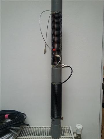
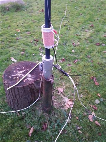
The complete coils construction
On this picture, both units are mounted together (sockets and tubes) and make it a stable construction.